Timer And Contactor R Relay Diagram - 3 Phase Contactor Connection Ewc May 2020 Youtube : Wiring diagram timer relay one of the most tough automotive repair jobs that a mechanic or repair service shop can.
Timer And Contactor R Relay Diagram - 3 Phase Contactor Connection Ewc May 2020 Youtube : Wiring diagram timer relay one of the most tough automotive repair jobs that a mechanic or repair service shop can.. How to contactor with timer wiring diagram and partical. When voltage is applied to the coil, the relay contacts remain in the off state and the set time begins. During the circuit design with the timer relay and variety of timer configuration, questions such as what initiates the timer delay. The following is a timing diagram of this relay contact's operation: In rlc, we use relay contactor mechanical timer counter etc.
Practice connect timer relay with start stop button,តម្លើង timer កំណត់ពេល. Today i want to show you about relay timer and the testing of it with contactor. Types, working and difference between them. Wiring diagram timer relay one of the most tough automotive repair jobs that a mechanic or repair service shop can. Timer and contactor wiring diagram source.
4 Pole Contactors For Power Switching Motor Protection And Control A Z Low Voltage Products Navigation Abb from www07.abb.com The lights stay on after parking car, and then. Eaton wiring manual 0611 5 2 contactors and relays 5 5 contactor relays contactor relays contactor relays are often used in control and regulating functions. Timer and contactor r relay diagram : Contactors and relays are electric switches. A wide variety of contactor relay timer options are available to you, such as time relay electrical relays and contactors use a low level control signal to switch a much higher voltage or current supply using a numer of different contact. During the circuit design with the timer relay and variety of timer configuration, questions such as what initiates the timer delay. Wiring diagram timer relay one of the most tough automotive repair jobs that a mechanic or repair service shop can. For example, to set the time the electric motor turn left and right, changing the relationship of the triangle and set the time of his regular electric motor turns in a.
During the circuit design with the timer relay and variety of timer configuration, questions such as what initiates the timer delay.
Contactors and relays are electric switches. A wide variety of contactor relay timer options are available to you, such as time relay electrical relays and contactors use a low level control signal to switch a much higher voltage or current supply using a numer of different contact. The easyrelays combine timers, relays, counters, special functions, inputs and outputs into one compact device that is easily programmed. How to contactor with timer wiring diagram and partical. The following is a timing diagram of this relay contact's operation: Eaton wiring manual 0611 5 2 contactors and relays 5 5 contactor relays contactor relays contactor relays are often used in control and regulating functions. Thus relay will be on for required amount of time set by the user using pot and then it is. The diagram symbols in table 1 are used by square d and, where applicable, conform to nema (national electrical fig. Timer and contactor r relay diagram : Engineering electrical diagram contactor and timer. Function of time delay relay is a timer for controlled equipment. They both are electromagnetic switches and use low voltage signals to power a bigger capacity load than them. Time delay relay schematic symbol.
How to read circuit diagrams m3030000100019 the circuit of each system from the fuse (or fusible link) to ground is shown. Engineering electrical diagram contactor and timer. Understanding all the time delay relay functions available in multifunctional timer can be an intimidating task. Geya timer relays come in various mount options, models, input voltage. Electrical diagrams contactor with timer.
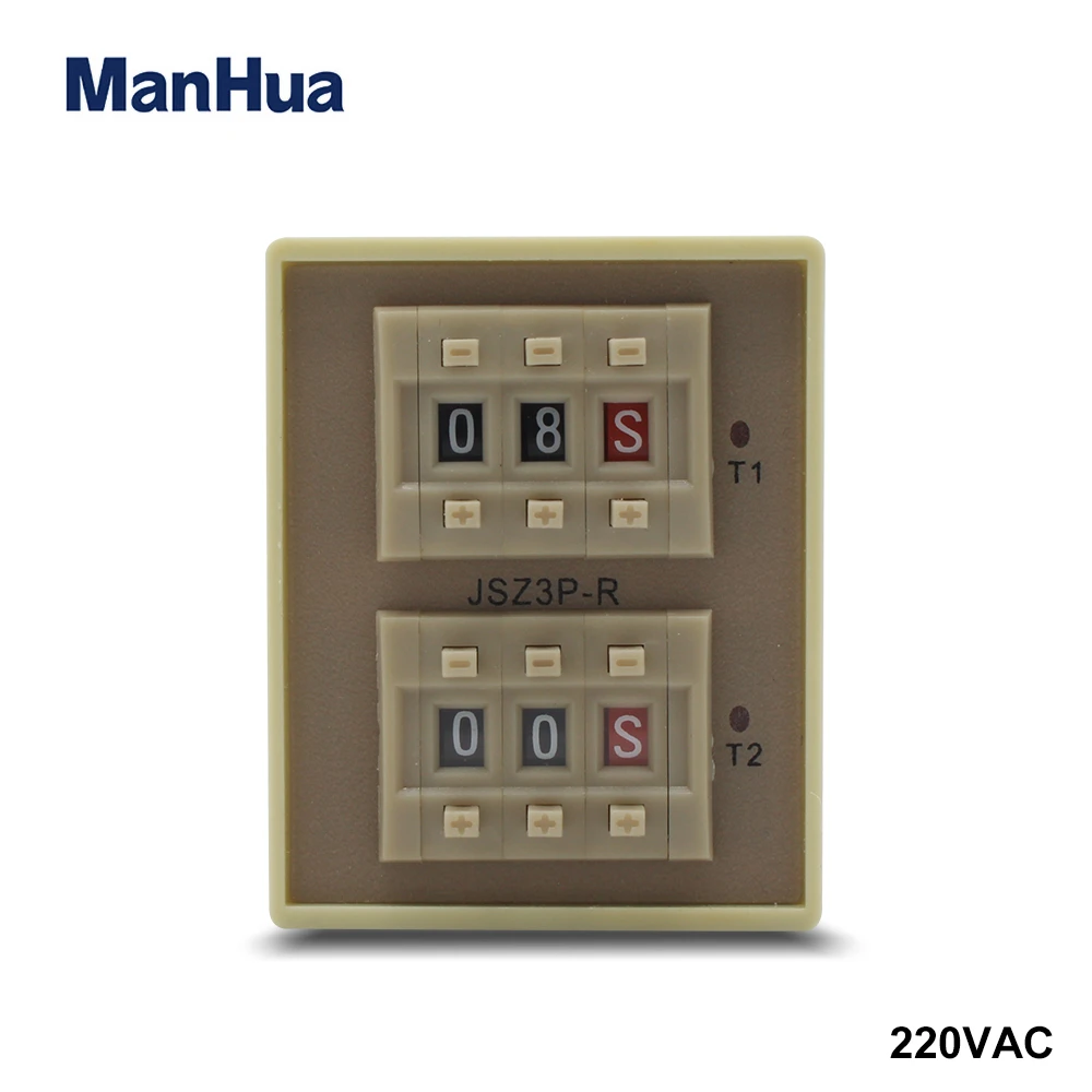
Manhua 220vac Sealed Cycle Delay Timer Relay Jsz3p R With 0 1s 99h Range Delay Timer Relay Timer Relaycycle Delay Timer Aliexpress from ae01.alicdn.com Time delay electromechanical relays worksheet digital circuits. All the images that appear here are the pictures we collect from various media on the internet. When voltage is applied to the coil, the relay contacts remain in the off state and the set time begins. Relays are used in low voltage circuits whereas contactor. In rlc, we use relay contactor mechanical timer counter etc. Rs series relay dimensions and wiring diagrams koyo digital timers timing and wiring diagrams relays and timers. How to wire contactor and overload relay. The lights stay on after parking car, and then.
Electrical diagrams contactor with timer.
Contactors and relays are electric switches. Timer and contactor wiring diagram source. Continuous current ratings for common a relay allows circuits to be switched by electrical equipment: Thus relay will be on for required amount of time set by the user using pot and then it is. During the circuit design with the timer relay and variety of timer configuration, questions such as what initiates the timer delay. In rlc, we use relay contactor mechanical timer counter etc. Class 9999 type xtd and xte. Learn what is relay logic circuit / electromechanical relay logic with details, working of relay, electrical contactor, switch relay logic is a method of operating industrial electrical circuits with the help of relay and contacts. Eaton wiring manual 0611 5 2 contactors and relays 5 5 contactor relays. It has a combination of versatility, the convenience of use, and installation and the ability to preserve panel space. I am looking to build a circuit that would control an output relay. Relays are used in low voltage circuits whereas contactor. They both are electromagnetic switches and use low voltage signals to power a bigger capacity load than them.
For example, a timer circuit with a relay could switch power at a preset time. Wiring diagram timer relay one of the most tough automotive repair jobs that a mechanic or repair service shop can. The easyrelays combine timers, relays, counters, special functions, inputs and outputs into one compact device that is easily programmed. Understanding all the time delay relay functions available in multifunctional timer can be an intimidating task. Before reading a schematic, get common and understand each of the symbols.
24 Volt Programmable Timer from waterheatertimer.org Relays and contactors are used for switching purposes in an electrical circuit. When voltage is applied to the coil, the relay contacts remain in the off state and the set time begins. Single phase timer and contactor wiring diagram. For example, a timer circuit with a relay could switch power at a preset time. Timer circuits used to provide time delays for triggering, types of timer circuits, ic 4060. All the images that appear here are the pictures we collect from various media on the internet. Function of time delay relay is a timer for controlled equipment. Timer and contactor r relay diagram :
For example, a timer circuit with a relay could switch power at a preset time.
Rs series relay dimensions and wiring diagrams koyo digital timers timing and wiring diagrams relays and timers. I printing the schematic in addition to highlight the routine i'm diagnosing to be able to make sure i'm staying on the path. Omron safety relay wiring diagram gallery. Ql series electromechanical relay specifications. Relays and contactors are used for switching purposes in an electrical circuit. Geya timer relays come in various mount options, models, input voltage. Engineering electrical diagram contactor and timer. In rlc, we use relay contactor mechanical timer counter etc. Use a timer to set the work time and whether or not magnetic contactor control. Contactors and relays are electric switches. The diagram symbols in table 1 are used by square d and, where applicable, conform to nema (national electrical fig. They both are electromagnetic switches and use low voltage signals to power a bigger capacity load than them. Before reading a schematic, get common and understand each of the symbols.


0 Komentar